In our Fabricator General series, we cover large projects or those with lots of building and construction and custom work. This week, we are taking a look at 3D printing from the design side with the second in a series of special guest posts from fellow SA Goon Dave “TKIY” Gordon. If you’re interested in the designs he’s talking about here but don’t feel up to making your own, you can find them on Dave’s Etsy store by clicking this link and following along with new designs on his Facebook page and Twitter.
Previously we’ve talked about creating a functional design for the Miracle Dice Holder, and how to combine the basic tools in Fusion 360 to get a flat shape with varying extrusions to give us something that will actually hold our dice. Today we are going to look at bringing in a vertical element to the design, making a multi-part object, and working with curves.
I Wish to Create Joinder
Since we want to create a vertical design with an angled face, we need to decide how to accomplish this. We could easily just slap a stand or plinth on the bottom of our design and pump out the STL but it’s going to need a ton of supports which adds print time, cost, and you also get a comparatively poor finish on the supported parts. We could print the design face down, but the dice sockets themselves would be bridged areas which again have a relatively poor finish, and since our angel wings and fleur de lis are not extruded to the same height as the dice sockets we would have supports there. The solution is to create a two part model with a mechanical connection.
The mechanical connection can be as complex or as simple as you like. As with most things, simple is better, so unless you need crazy precision or have a specific requirement for something like orientation or strength, a simple square peg does the trick.
Flip over the model and sketch a 10mm x 10mm square in the centre of the dice holder, and extrude it 5mm deep into the model. That’s all you need for a firm connection.

Plinth – /plinTH/ – Noun – a Heavy Base Supporting a Statue or Vase
Well it’s neither a statue nor a vase but it’s close enough.
Designing the plinth can be as interesting as designing the dice holder itself, and options here are endless. You can go as heavy on the design elements as you want, adding multiple layers, face treatments, whatever you like so long as we remember that we need a functional design first and foremost.
In this case we have a wide design that will likely be somewhat top-heavy, so in order to keep it functional our plinth should be wide enough and low enough so that the holder won’t tip over too easily. There is some trial and error in getting this right, but generally I wanted the plinth to keep the holder tilted about 15 degrees and held just above the table surface. You can do math here if you like, but I’ve just estimated that the total height of the plinth should be about 25-30mm.
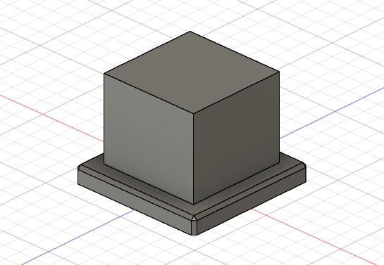
To keep it all stable, the base should be about 50% wider than it is tall. Again just a guess, but that ratio seems to work for me in the few designs I’ve done like this. So we start a new design, and sketch a 40mm x 40mm square on the origin layer and extrude it 5mm to give us something to build on. Much like the holder design, we don’t want the edges too square, but instead of using a filet, this time I chamfer the corners and top edges.
Sticking with a chamfer instead of using a filet again is just a design choice. I want the plinth to be a little more formal.
Now let’s get some height. On the surface of our 40mm square I create another 30mm x 30mm square and extrude it 25mm to give us the height that we want. This is the basic vertical shape we can start with before adding the curves to make the plinth match our overall design.
Curved, Unlike the Earth
There are a million different ways to generate curves in a tool like Fusion 360; the cylinder, loft, torus, sphere and pipe tools to name a few, but if you want to generate a curve with fine control over the shape, it’s often easiest to sketch on a body and then use that sketch to cut the curve in. Using tools like 3-point arc lets you connect any two points and then refine the curve to your liking.
Using the layout grid and the 3-point arc tool, I define two mirrored sketches on the front face of the plinth.
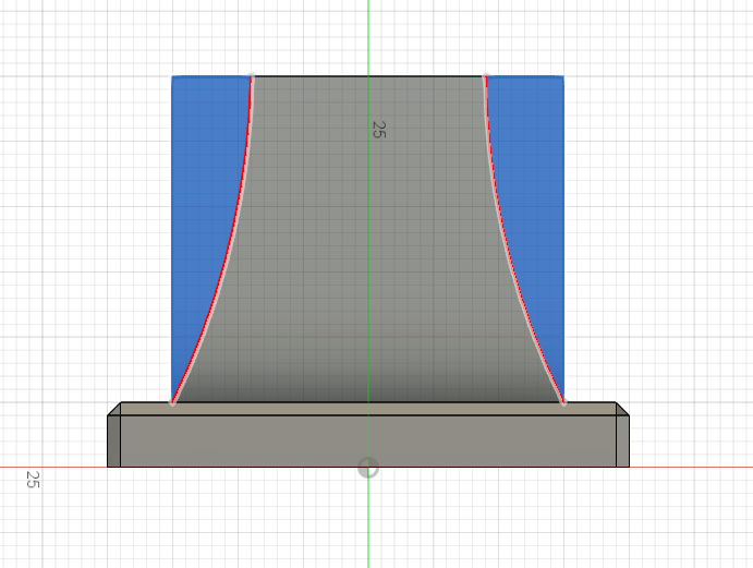
By extruding and cutting this sketch, and then repeating the same steps on the side of the plinth, you can create a profile to your liking. Since Fusion keeps a history of each step in the design process you can go back and alter the sketches until you are happy with the final result.
One thing to note, once a face of an object is curved you can no longer treat it as a face for sketches. For instance, if I wanted to now add text to the front on the plinth we could not select the face and place the text on it. Just something to keep in mind when working with curves.
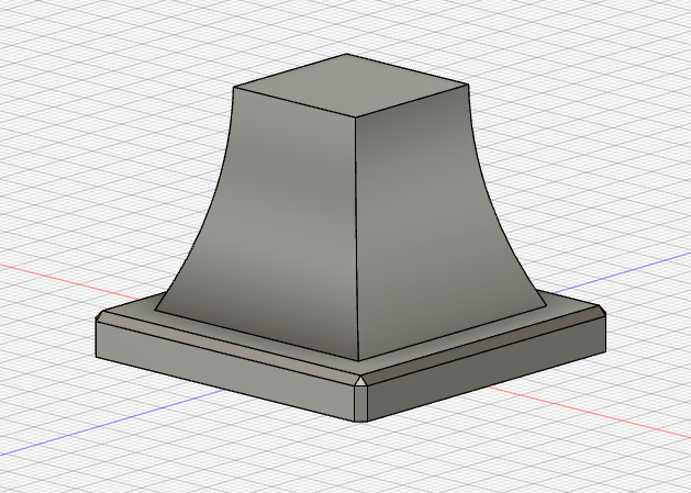
The Angle of the Dangle
We now have a plinth that will support the dice holder, but our goal was one that would hold the dice at an angle so that it’s easier to see when sitting as well as standing at the table. The angle is up to you to decide but when I did the initial design, I settled on a 15 degree angle which seems to work well.
Adding the angle to the top of the plinth is just like adding the curve to the front and side – sketch, then extrude and cut. However, since our faces are all curved, we can’t sketch on the face itself. Instead draw your sketch on the origin layer, and when you extrude, chose ‘Symmetric’ for the direction to cut:
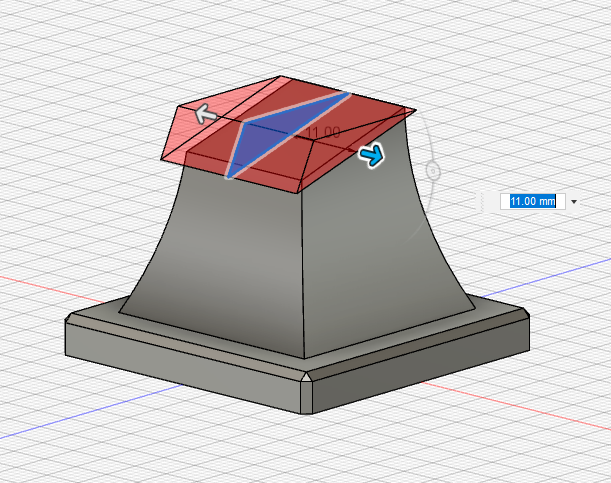
The final step is to create the “male” end of our connection to the dice holder. We have a 10mm x 10mm square cut 5mm deep into the dice holder, but if you recall from part one, 10mm is never 10mm. Extrusion variances happen all the time in 3D printing, and while it might not seem like a big issue, even a tenth of a millimeter can make a joint that either won’t fit, or will fit so tightly that you risk breaking the pieces putting them together or taking them apart.
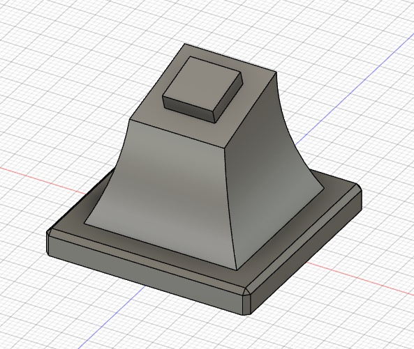
Give yourself some leeway when creating the matching square on the plinth, 9.8mm x 9.8mm extruded 4.8mm. The Plinth is done!
Tune in next week for the final part of this series we will cover the assemble menu, as well as version one of this design and why it was never produced.
You can find more of Dave’s designs in his Etsy shop.
If you have any questions or feedback, drop us a note in the comments below or email us at contact@goonhammer.com.